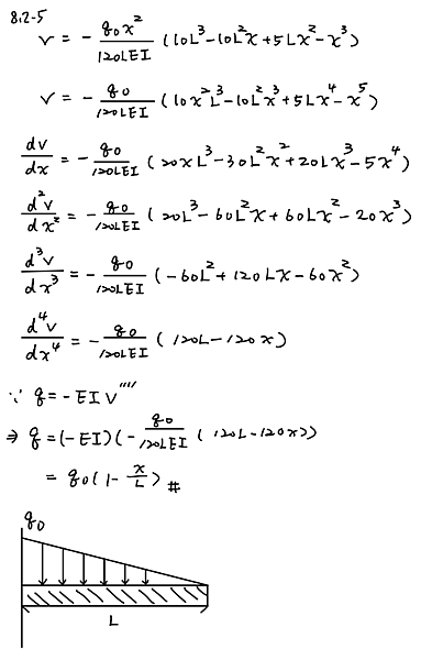
The deflection curve for a cantilever beam AB (see figure) is given by the following equation: upsilon (x) = - w_0 x^2/360L^2EI (45L^4 - 40 L^3x + 15 L^2x^2 - x^4)
describe the load acting on the beam
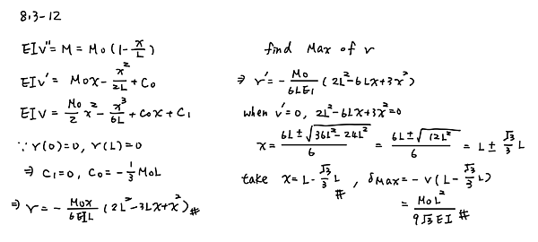
Derive the equations of the deflection curve for a simple beam AB loaded by a couple Mo acting at distance a from the left-hand support (see figure) Also, determine the deflection δ0 at the point where the load is applied. Use the second-order differential equation of the deflection curve.
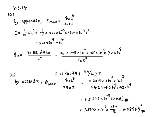
A cantilever beam has a length L = 3.6 m and a rectangular cross section (b = 400 mm, h = 600 mm). A linearly varying distributed load with peak intensity q0 acts on the beam.
(a) Find peak intensity q0 if the deflection at joint B is known to be 4.5 mm. Assume that modulus E = 205 GPa.
(b) Find the location and magnitude of the maximum rotation of the beam.
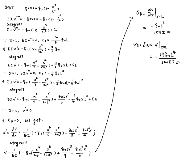
A cantilever beam AB is subjected to a parabolically varying load of intensity q = q_0(L^2 - x^2)/L^2, where q_0 is the maximum intensity of the load (see figure). Derive the equation of the deflection curve, and then determine the deflection delta_B and angle of rotation theta_B at the free end. Use the fourth-order differential equation of the deflection curve (the load equation).
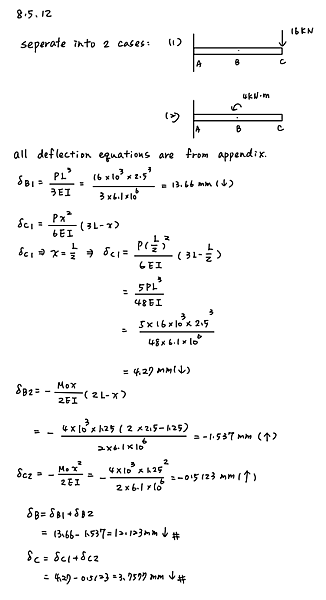
The cantilever beam ACB shown in the figure has flexural rigidity EI = 2.1 Times 106 k - in.2 Calculate the downward deflections delta C and delta B at points C and B, respectively, due to the simultaneous action of the moment of 35 k - in. applied at point C and the concentrated load of 2.5 k applied at the free end B.
A simple beam AB supports a uniform load of intensity q=6.0 kN/m over a portion of the span (see figure). Assuming that L= 10 m, a= 4 m, and b = 2 m, draw the shear-force and bending-moment diagrams for this beam. q = 6,0 kN/m a-4 m b-2m


 留言列表
留言列表


